|
|
Cockpit Communications Using V+
feature author: Paul Halliday
The cockpit communications requirements for the Beech
1900D simulator were not that rigorous. There were two pilot stations, each with
two microphones (regular headset and oxygen mask), an Instructor station,
and an Observer station. The voice communications for the
simulator were set up using the following requirements.
-
There are four stations: Pilot, CoPilot,
Instructor, and Observer.
-
The Pilot and CoPilot voice communications
function as in the real aircraft.
-
The Instructor and Observer always hear
the Pilot and CoPilot.
-
When either the Pilot or CoPilot use a PTT, the
volume of their voices will increase to full in the Instructor and
Observerís headsets. Otherwise the volume of their voices will
remain at half.
-
If the Hot Interphone switch is on, the volume
of both the Pilot and CoPilotís voices will increase to full.
-
The Instructor may transmit to the Pilot,
CoPilot, both, or neither.
-
The Instructorís microphone is always
transmitting to the Observerís headset at a half-volume side-tone.
-
The Instructorís microphone is always
transmitting to the Instructorís headset at a half-volume side-tone.
-
The Observerís microphone is always
transmitting to the Instructorís headset at a half-volume side-tone.
-
The Observerís microphone is always
transmitting to the Observerís headset at a half-volume side-tone.
Controls that affect communications are shown in Table
3.
|
|
|
|
Pilot
|
Audio control panel, COM 1 switch
|
|
Pilot
|
Audio control panel, COM 2 switch
|
|
Pilot
|
Audio control panel, speaker switch
|
|
Pilot
|
Audio control panel, speaker volume
|
|
Pilot
|
Audio control panel, headset volume
|
|
Pilot
|
Audio control panel, transmit selector (PA, COM 1, COM 2)
|
|
Pilot
|
Yoke, Comm radio Push-To-Talk (PTT) switch
|
|
Pilot
|
Yoke, Interphone PTT switch
|
|
Pilot
|
Overhead panel, Mic/Mask selector switch (Normal, Oxygen Mask)
|
|
CoPilot
|
Audio control panel, COM 1 switch
|
|
CoPilot
|
Audio control panel, COM 2 switch
|
|
CoPilot
|
Audio control panel, speaker switch
|
|
CoPilot
|
Audio control panel, speaker volume
|
|
CoPilot
|
Audio control panel, headset volume
|
|
CoPilot
|
Audio control panel, transmit selector (PA, COM 1, COM 2)
|
|
CoPilot
|
Yoke,
Comm radio PTT switch
|
|
CoPilot
|
Yoke, Interphone PTT switch
|
|
CoPilot
|
Overhead panel, Mic/Mask selector switch (Normal, Oxygen Mask)
|
|
Pilot/CoPilot
|
Audio control panel, Hot interphone switch
|
|
Instructor
|
Transmit selector (None, Pilot, CoPilot, Both)
|
|
|
For the most part, the designs that follow use simple
logic to combine these controls in such a way as to provide signals to the
outputs, which are controls ports for the FX-30 mixer. This mixer is a
Commercial-Off-The-Shelf (COTS) product manufactured by SimPhonics, and is
composed of two separate cards working together. It plays an integral part
in the processing of voice signals and signals coming from players in the
NAV_DME, Marker, ADF, and ATIS V+ designs discussed in this article. A
custom patch panel and cable had to be produced for the Beech 1900D
simulator. The patch panel was manufactured by TDI, and SimPhonics
manufactured the cable.
Iíve been involved in building several simulators and
when it comes to voice communications for these simulators, it has always
been a very difficult, one-of-a-kind problem to solve. This doesnít have
to be a nightmare! With the Audio 16 card coupled with the ISA-30 DSP,
a 16 by 16 input/output matrix allows you to direct any of 16 separate
inputs to any of 16 separate outputs. And itís all made simple byÖ you
got it Ė V+.
For the Beech 1900D simulator, we only needed 12 of the
16 available FX-30 inputs, and 6 of the available 16 FX-30 outputs for
taking care of the voice communications requirements. The FX-30 allocated
channels for the inputs are shown in Table
4. Note that players dealing with nav audio are treated as inputs to
the FX-30 (they come out of the player and into the FX-30). The output of
the ATIS system is also an input to the FX-30.
|
1
|
Pilot Headset Microphone
|
|
2
|
Pilot Oxygen Microphone
|
|
3
|
Pilot Handheld Microphone
|
|
4
|
CoPilot Headset Microphone
|
|
5
|
CoPilot Oxygen Microphone
|
|
6
|
CoPilot Handheld Microphone
|
|
7
|
Instructor Headset Microphone
|
|
8
|
Observer Headset Microphone
|
|
9
|
Pilot Nav Audio
|
|
10
|
CoPilot Nav Audio
|
|
11
|
Installed spare
|
|
12
|
<>ATIS Audio Output, left channel
|
|
13
|
ATIS Audio Output, right channel
|
|
14 - 16
|
Installed Spares
|
|
1
|
Pilot Headset
|
|
2
|
CoPilot Headset
|
|
3
|
Instructor Headset
|
|
4
|
Observer Headset
|
|
5
|
Pilot Overhead Output to Speaker Amplifier
|
|
6
|
CoPilot Overhead Output to Speaker Amplifier
|
|
7 - 16
|
Installed Spares
|
The FX-30 allocated channels for the outputs are shown
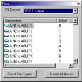
in Table 5. Each FX-30 output has 16 inputs and one master gain associated with
it. These 17 items per FX-30 output are treated as output ports in a list
shown in Figure 46 (you need to select the DSP 1 Output I/O Device at the top of the
Ports window to see the list shown in the figure).

Figure 46.
DSP Output Ports
These two cards constitute the FX-30 system,
which is part of the SimPhonics computer system.
|
|
|


