|
|
|
|
|
|
|
|||||||||||||||||||
|
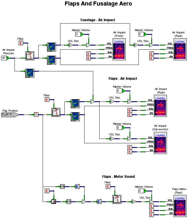
Flaps and Fuselage Aero Design
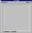
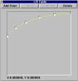
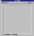
The Flaps and Fuselage Aero V+ design is shown in Figure 15. This worksheet models sounds for air impact on the fuselage, air impact on the flaps, and the flaps motor. We’ll discuss each of these models separately. The Fuselage - Air Impact model has one input and two players. The players play the same sound on the front speakers and the rear speakers. The balance and enable inputs are constantly 0 and 1 respectively. The input Air Impact Pressure is passed through a First Order Low Pass Filter, which then splits into two paths for volume and frequency. The low pass filter is used to smooth any abrupt changes in air impact. Let’s analyze what sound effects occur as an aircraft’s nose passes through air. As the air impact increases, the sound of the wind passing over the windscreen increases in volume, while its pitch also increases. The volume path for both players passes through a Float LFI. As shown in Figure 10, the volume starts at 0, rapidly increases, and then begins to level out to a maximum of 100%. The frequency path for both players goes through a Float LFI, Figure 11, that starts at about 60%, and gradually increases to 100% as the air impact increases.
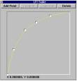
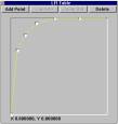
The Flaps - Air Impact model has two inputs and two players. The players play the same sound on the rear speakers and the sub-woofer. The balance and enable inputs are constantly 0 and 1 respectively. The Flaps Position input passes through a First Order Low Pass Filter, which then splits into two paths for volume and frequency. Volume for the players is a function of air impact and flaps position. Air impact if fed to the LFI shown in Figure 12, whose curve starts at 0 and increases to 1. Figure 13 is the LFI for the flaps position that feeds the volume. The curve starts at 0, rapidly increases, and levels out to a maximum of 1. The frequency for the players is a function of flaps position only. This is passed to the LFI shown in Figure 14. Note that as the flaps surface increases, the frequency is lowered. This, coupled with playing the sound on the sub-woofer, gives a very low frequency noise rumble when flaps position and speed is increased. It will, in fact, begin to rattle the cockpit if taken to the extreme.
The Flaps – Motor Sound model has one input and one player. The player plays the motor sound on the rear speakers. The frequency, balance, and enable inputs are constantly 1, 0, and 1 respectively. The flaps position input passes through a First Order High Pass Filter, which is then multiplied by the flaps position input to produce an output as long as the flaps position is changing. A First Order Low Pass Filter is then used to smooth out any abrupt changes in flaps position coming from the host computer. The output of the low pass filter is then provided as volume input to the flaps motor sound player.
Figure 15. Flaps and Fuselage Aero Design A balance of 0 plays equally to both channels of a player. Each player has two channels: left and right. A value of -1 is “panned” all the way to the left, and a value 1 is panned all the way to the right. |
|
|
||||||||||||||||||
|
|
|||
| Home | About | Products | Support | News | Find | Contact Us | |||
|
©SimPhonics Legal Notices Privacy Policy |
|||