|
|
VComm Radio Scan Channel |
|
ID: 2084 |
|
|
VComm Radio Scan Channel |
|
ID: 2084 |
|
Object Description |
|
|
The VComm Radio Scan Channel objects are used in conjunction with a VComm Scanner object to simulate the operation of a radio that scans multiple frequencies. Although there are many variations in how such radios work, in general, such a radio will silently scan all of its frequencies until a signal is detected on one of them. Upon signal detection, the radio will dwell (i.e., stay) on that frequency until the signal ceases. During the dwell, the radio operator listens to the transmission. After the signal ceases, the radio stays on the dwelled frequency for a period of time to allow the radio operator to transmit a reply. After a period of inactivity on that frequency (i.e., no signals detected and no transmissions made), the radio resumes scanning. The VComm Radio Scan Channel object is used to associate radio objects and channel numbers to a VComm Scanner. |
|
|
Input Pins |
|
|
Scanner |
Each VComm Scanner object produces a unique scanner handle. The Handle output pin on the VComm Scanner object must be connected to this Scanner input pin. |
|
Enable |
The Enable pin enables the channel represented by this object. A value of zero disables the channel. Any non-zero value enables the channel. A disabled channel is ignored by the VComm Scanner object. The outputs of this object are set to zero when it is disabled. |
|
Radio |
Radio handle from either the VComm GENERIC Radio, V8 DIS Only or VComm GENERIC Radio, V8 DIS/HLA radio objects. |
|
Output Pins |
|
|
Rx |
The Rx pin is controlled by the VComm Scanner object and provides the state of reception on the channel. A value of 0 indicates that reception is disabled. A value of 1 indicates that reception is enabled. |
|
Tx |
The Tx pin is controlled by the VComm Scanner object and provides the state of transmission on the channel. A value of 0 indicates that transmission is disabled. A value of 1 indicates that transmission is enabled. |
|
Static Data |
|
|
Channel Number |
This value specifies the channel number of this channel. Valid channel numbers range from 0 to 9. Each VComm Radio Scan Channel associated with the same VComm Scanner must have a unique channel number. |
|
Example |
|
|
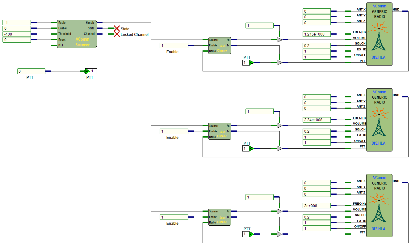
The example below presents a design for a scanning radio with three channels. Each channel is represented by a VComm Generic Radio, V8 DIS/HLA object (VComm Generic Radio, V8 DIS Only objects may be used as well). The VComm Scanner object is associated to each one of its channels via a VComm Radio Scan Channel object. The channels must be numbered uniquely using the Channel static data value of each VComm Radio Scan Channel object. Several static data values in the VComm Scanner object refer to these channel numbers.
The VComm Scanner object monitors incoming signal levels on all of its associated radios. Based on the incoming signal levels the object controls an internal state machine and controls the Rx (Receive) and Tx (Transmit) output pins on the VComm Radio Scan Channel objects. Those output pins are then used to control the volume and the PTT on their associated radio. It is important to note that although this is a simulation of a single scanning radio, it requires as many radio objects as there are channels to scan for the radio. |
|
